Automotive A/C Compressor
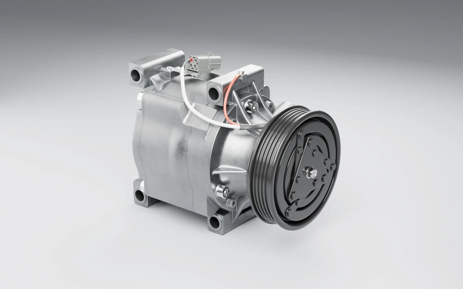
A belt-driven vehicle A/C compressor with an electromagnetic clutch, showing high discharge pressure, a leaking charge, liquid at suction and a circuit opened while charged.
Normal operation. Engine running and A/C on: the clutch is engaged, the shaft turns with the pulley, and the compressor draws vapour from the evaporator and delivers it hot and at high pressure to the condenser. Where the circuit settles depends on the ambient temperature, the airflow over the condenser and the evaporator, the engine speed and the charge, so a pressure means something only against the vehicle's own service data — and this model carries none.
Deviation library
Components
Explore the equipment
Raise the refrigerant in a vehicle's air-conditioning circuit from evaporator pressure to condenser pressure, so the circuit can reject at the condenser the heat it picked up in the cabin. Low-pressure vapour is drawn from the evaporator through the suction port and delivered hot and at high pressure to the condenser through the discharge port; the compressor oil travels round the circuit with the refrigerant and depends on it to come back. This is a belt-driven unit with an electromagnetic clutch: the pulley turns whenever the engine runs, and the compressor only pumps while the clutch coil is energised and holds the armature against the pulley face. It is an automotive part, not process plant, and it carries no tags, because nothing on a vehicle is tagged the way a P&ID is. The model is the exterior of the unit as supplied, with plastic transit covers still on the refrigerant ports and no belt, lines or bracket. It does not show the pumping mechanism, so whether this is a piston, swash-plate or scroll design cannot be read from it; nor can the refrigerant it was built for — R-134a and R-1234yf circuits take different service couplers and are not interchangeable — whether a pressure relief valve is fitted, or how the vehicle controls the clutch. Read all four from the part number and the vehicle's service information before working any case here.
Components
Compressor housing
The cast body of the compressor — front head, body and rear head — with the mounting lugs that bolt it to the engine's bracket. It is the pressure boundary for both sides of the circuit, suction on one side of the internal valves and discharge on the other, and it contains the pumping mechanism and its oil, none of which is modelled.
Normally: Bolted rigidly to its bracket and sealed at every joint, with the suction side running cool and the discharge side warm while it pumps.
Pulley and clutch
The belt pulley, the clutch armature plate on its face and the nut that holds the armature hub on the drive shaft. The pulley runs on its own bearing and turns with the engine whatever the clutch is doing. The field coil sits inside the pulley and is not modelled separately; energised, it pulls the armature onto the pulley face and couples the drive to the shaft. Behind the hub, and also not modelled, the shaft seal is the boundary between the circuit and atmosphere where the shaft leaves the housing.
Normally: Pulley turning freely with the belt; armature held clear by its springs with the A/C off, and clamped flat to the pulley face without slip or noise when the clutch is commanded on.
Refrigerant ports (transit covers fitted)
The suction and discharge connections, on one port face on the side of the housing. The model shows them as the compressor is shipped, under a plastic cover plate and cap that keep moisture and dirt out until the lines are fitted, and does not mark which port is which. In service the line manifold is bolted over them on O-rings or a gasket, and those seals are among the commonest leak points in the circuit.
Normally: In service: manifold bolted down on new seals, with no oil staining at the joint. As modelled: covers on, and staying on until the lines are ready to fit.
Clutch connector
The electrical connector through which the vehicle's control system supplies the clutch coil. Whatever decides whether the compressor runs — the A/C request, the pressure switch or transducer, the evaporator temperature control, the engine management — acts on the compressor through this one connection.
Normally: Mated and latched, seal intact, terminals clean and no strain on the harness.
Clutch leads
The two leads, with their sheathing and retaining clips, that carry the coil supply from the connector over the housing to the field coil behind the pulley.
Normally: Clipped clear of the belt, the pulley and the hottest parts of the housing, with the insulation unbroken.
Housing bolting
The bolts that hold the front head, body and rear head together and retain the port face and the clutch. The joints they clamp are pressure joints on a charged circuit.
Normally: All present and tight, with no oil weeping from the joints they clamp.
Operating states
Charged, engine off
The circuit is sealed and full of refrigerant at a standing pressure set by the ambient temperature, not by the compressor — once it has equalised it is the same on both sides, and it is never zero. Nothing moves, but every port, seal and hose is holding pressure, and opening any of them releases refrigerant and oil. This is how most people find the compressor when they come to work on it, which is why the circuit is treated as charged until a recovery machine has shown it is not.
Normal operation
Engine running and A/C on: the clutch is engaged, the shaft turns with the pulley, and the compressor draws vapour from the evaporator and delivers it hot and at high pressure to the condenser. Where the circuit settles depends on the ambient temperature, the airflow over the condenser and the evaporator, the engine speed and the charge, so a pressure means something only against the vehicle's own service data — and this model carries none.
Engine running, A/C off
The clutch is released: the pulley spins on its bearing with the belt while the armature and the shaft stand still. The compressor is not pumping, but the drive is live, and the clutch can be commanded on at any moment. That is why hands, tools and loose clothing stay clear of the belt and the front of the compressor whenever the engine is running.
Clutch cycling
On clutch-cycling systems the control engages and releases the clutch repeatedly to keep the evaporator above freezing and the pressures in range; at light cooling load it cycles more often, at heavy load it stays engaged longer. Rapid short-cycling is a symptom rather than a state — most often a low charge, with suction pressure hovering at the low-pressure cut-out. Variable-displacement compressors control capacity internally instead, and the model cannot say which kind this is.
Recovered for service
The refrigerant has been recovered with a recovery machine, never vented, and the circuit is at atmospheric pressure, so it can be opened. Open ports let in air and moisture, which vehicle compressor oils absorb readily, so covers or caps go back on whenever a connection is left open — the model shows them as they arrive on a new unit. After the repair the circuit is leak-tested and evacuated, then charged by weight with the refrigerant and oil the vehicle specifies.
Failure scenarios and safeguards
MOREPressure
The cut-out releases the clutch and the system stops cooling until the pressure falls — warm air at idle, for the driver — and the technician traces the cause to the fan, the condenser or the charge.
Causes
- Condenser fan not running — a failed motor, relay or fuse, or a control fault
- Condenser face blocked by leaves, insects or road dirt, or fins flattened so air cannot pass
- Circuit overcharged with refrigerant or oil
- Air or another non-condensable gas left in the circuit by an incomplete evacuation
- A restriction on the high side — a blocked expansion valve or orifice tube, a saturated receiver-drier, a kinked line
How it develops
- 01Heat is not being rejected at the condenser fast enough, or flow is restricted downstream, so pressure builds on the high side and backs up to the discharge port.
- 02The compressor is now pumping against a higher head. The discharge side of the housing runs hotter, and the torque the clutch and the belt have to carry rises with it.
- 03The high-pressure cut-out reads the rise and the control system de-energises the clutch through the connector. The armature releases and the compressor stops pumping, while the pulley carries on turning.
- 04If the clutch is not released, the pressure keeps climbing until something gives — the pressure relief valve where one is fitted, otherwise the weakest joint: the seals at the port face, a hose, a housing joint.
Safeguards
High-pressure cut-out
A pressure switch or transducer on the high side — on the vehicle's lines or receiver-drier, not on the compressor, so not in this model — tells the control system that discharge pressure is too high, and the clutch is released before the circuit reaches a pressure its parts were not built to hold.
If it fails: The compressor keeps pumping against a rising head. The pressure relief valve, where one is fitted, becomes the only protection; where none is, the weakest joint on the high side is.
Condenser fan and airflow
The condenser fan, switched by the control system, keeps air moving across the condenser when the airflow from driving is not enough — at idle, in traffic, and with the vehicle standing in a workshop. Rejecting heat at the condenser is what keeps discharge pressure down in the first place.
If it fails: Discharge pressure climbs whenever the vehicle is not moving — which is exactly when someone is standing beside it under the bonnet.
Compressor pressure relief valve, where fitted
A spring-loaded valve on the high side of many compressors that opens if discharge pressure rises past what the circuit can tolerate, venting refrigerant and oil to atmosphere and reseating as the pressure falls. It protects the hardware, not the people next to it: it discharges under the bonnet. The model does not show whether this unit has one.
If it fails: With no relief path, or one that does not lift, the pressure finds the weakest point instead — a hose, a seal at the port face, a housing joint — and the release is uncontrolled.
Charge by weight to the vehicle specification
The circuit is charged with the quantity, refrigerant and oil the vehicle's label and service data specify, weighed in by a charging station rather than judged from gauges or topped up. An overcharge and an undercharge are both causes on this worksheet.
If it fails: The circuit carries too much refrigerant or oil, too little, or the wrong kind, and the deviations that follow start the first time the clutch engages.
Unmitigated: With the cut-out failed, the relief valve lifts and dumps refrigerant and oil under the bonnet; without one, a seal or a hose fails instead. The release is hot, under pressure and beside a running engine, next to exhaust parts where R-1234yf can ignite and either refrigerant can break down into hydrogen fluoride.
LESSRefrigerant charge
The low-pressure cut-out stops the compressor running on a low charge. Cooling is lost, the leak is found with a detector or dye at service and repaired, and the circuit is evacuated and charged by weight.
Causes
- Seals at the port face, O-rings at the line joints, or the shaft seal leaking
- A hose or line chafed, corroded or holed, or a condenser struck by road debris
- A housing joint weeping
- Undercharged at the last service, or topped up instead of recovered and charged by weight
How it develops
- 01Refrigerant escapes at a joint and carries oil out with it; an oily, dirt-stained patch around a fitting is usually the first thing anyone sees.
- 02As the charge falls, suction pressure and flow fall with it. Less refrigerant reaching the compressor means less to cool it and less oil carried back to it.
- 03The low-pressure cut-out refuses or releases the clutch. Before it does, the clutch often short-cycles as the suction pressure hovers around the switch.
- 04Kept running starved, the compressor overheats and its internals lose lubrication until wear becomes seizure. The shaft locks, and an engaged clutch is now coupling a moving belt to a shaft that will not turn.
Safeguards
Low-pressure cut-out
A switch or transducer that stops the clutch engaging, or releases it, when the low-side pressure is too low — usually because the charge has leaked away. It protects the compressor from running without enough refrigerant to cool it and bring its oil back.
If it fails: The compressor runs starved, overheating and losing lubrication, and the next thing to happen is a seizure rather than poor cooling.
Leak test after repair
Before it is charged, a repaired circuit is proved tight — a pressure or vacuum hold, then an electronic detector or dye check at the joints — so a leak is found in the workshop rather than as a slow loss of charge in service.
If it fails: The circuit is charged with a leak in it. The charge bleeds away until the low-pressure cut-out acts, or the compressor runs on whatever is left.
Charge by weight to the vehicle specification
The circuit is charged with the quantity, refrigerant and oil the vehicle's label and service data specify, weighed in by a charging station rather than judged from gauges or topped up. An overcharge and an undercharge are both causes on this worksheet.
If it fails: The circuit carries too much refrigerant or oil, too little, or the wrong kind, and the deviations that follow start the first time the clutch engages.
Clutch and harness inspection
The clutch air gap, the coil supply, and the state of the connector and leads are checked at service against the vehicle data. A clutch that slips or will not pull in is more often an air gap or a supply fault than a failed compressor.
If it fails: A slipping clutch stays in service, heating the pulley bearing and the armature until one of them fails.
Unmitigated: The compressor seizes. The clutch slips and burns against the locked hub, or the belt is thrown or snaps — and on vehicles where the same belt drives the alternator or the water pump, they stop with it. Debris from the failed compressor is carried round the circuit, so fitting a new compressor alone does not end the repair.
AS WELL ASPhase at suction
Evaporator temperature control cycles the clutch or cuts capacity before the evaporator ices, and a charge weighed in to specification leaves no excess liquid to come back.
Causes
- Expansion valve stuck open, flooding the evaporator
- Evaporator airflow lost — a failed blower, a blocked cabin filter or evaporator face, an iced evaporator
- Circuit overcharged with refrigerant
- Oil added at service on top of what the circuit already holds
How it develops
- 01Refrigerant that has not fully evaporated, or a slug of oil, arrives at the suction port with the vapour.
- 02Liquid does not compress. Inside the housing it is forced through passages sized for vapour, loading the internal valves and the drive far beyond their duty — heard from outside as knocking.
- 03The shock travels back through the shaft to the clutch and the shaft seal. Repeated, it breaks internal valves and damages the seal, and the leak that follows starts the LESS charge deviation.
Safeguards
Evaporator temperature control
A thermostat, a temperature sensor or the compressor's own displacement control limits how cold the evaporator gets, cycling the clutch or reducing capacity so the evaporator does not ice over and liquid does not come back to the compressor.
If it fails: The evaporator ices, airflow through it collapses, and refrigerant that should have evaporated returns to the suction port as liquid.
Charge by weight to the vehicle specification
The circuit is charged with the quantity, refrigerant and oil the vehicle's label and service data specify, weighed in by a charging station rather than judged from gauges or topped up. An overcharge and an undercharge are both causes on this worksheet.
If it fails: The circuit carries too much refrigerant or oil, too little, or the wrong kind, and the deviations that follow start the first time the clutch engages.
Unmitigated: Broken internal valves and a seized compressor, or a damaged shaft seal releasing refrigerant and oil at the front of the compressor, beside the spinning pulley.
OTHER THANMaintenance procedure
Recovery before the circuit is opened leaves nothing behind the joint, eye and hand protection deal with the residue, and the work is done in a ventilated bay away from pits and ignition sources.
Causes
- Lines or the compressor removed without the refrigerant being recovered first
- Recovery stopped early, with liquid still trapped in part of the circuit
- A service coupler or valve core disturbed while the circuit is charged
- A joint loosened to relieve a sticking fitting, on a circuit assumed to be empty
How it develops
- 01A joint on a charged circuit is loosened. Behind it is the standing pressure of the whole circuit, not a small residue.
- 02Liquid refrigerant and oil jet from the joint and flash to vapour as they leave it, freezing whatever they touch — the fitting, the spanner, the hand holding it.
- 03The vapour is heavier than air and sinks, collecting under the vehicle and in any pit beneath it. Where it meets a flame, a heater or a hot engine part, R-1234yf can ignite and either refrigerant can break down into acid gas.
Safeguards
Recovery before the circuit is opened
Before any line, port or fitting is disturbed, the refrigerant is recovered with a recovery machine and the circuit confirmed at atmospheric pressure, by a technician qualified for vehicle air-conditioning work where the jurisdiction requires it. Recovered refrigerant is never vented.
If it fails: A charged circuit is opened: liquid refrigerant and oil spray from the joint and flash to vapour, at the hands and face of whoever is holding the spanner.
Eye and hand protection
Safety glasses or goggles, and gloves suited to refrigerant work, whenever the circuit is connected to, opened or charged. Liquid refrigerant flashing to vapour freezes skin and eye tissue on contact.
If it fails: A spray that would have been an inconvenience becomes a cold burn to the hands or an injury to the eye.
Ventilated bay, clear of pits and ignition sources
Refrigerant work is done in a ventilated bay, away from pits and below-ground spaces where refrigerant vapour — heavier than air — collects, and away from naked flames and hot work. R-1234yf is classed as mildly flammable, and both common vehicle refrigerants break down into toxic products, hydrogen fluoride among them, when they meet a flame or a very hot surface.
If it fails: Released vapour collects where people are working and displaces the air; where it reaches a flame, a heater or a hot exhaust part, R-1234yf can ignite and either refrigerant can decompose into acid gas.
Unmitigated: Cold burns to the hands and face and injury to the eyes from the spray, refrigerant vapour building up in a pit where someone is working, and — where it reaches a flame or a hot surface — fire or toxic decomposition products. The refrigerant itself is lost to atmosphere, which is what the recovery requirement exists to prevent.
MOREClutch slip
The slip is found at service, with the air gap and the coil supply checked against the vehicle data, and the clutch or the connector is put right before the bearing is damaged.
Causes
- Clutch air gap grown with wear, so the coil can no longer pull the armature fully in
- Low voltage at the coil — a corroded or loose connector terminal, a damaged lead
- Oil or refrigerant on the friction faces, often from a leaking shaft seal
- The compressor tightening internally and demanding more torque than the clutch can carry
How it develops
- 01The coil is weakly energised, or the gap is too wide for it, so the armature is drawn towards the pulley without being clamped to it.
- 02Pulley and armature run against each other at different speeds, and the friction becomes heat at the clutch face — a burning smell, and discolouration on the armature.
- 03The heat soaks into the pulley bearing, the coil and any lead routed close to the front of the compressor. The bearing dries out and fails, or the coil insulation breaks down.
Safeguards
Clutch and harness inspection
The clutch air gap, the coil supply, and the state of the connector and leads are checked at service against the vehicle data. A clutch that slips or will not pull in is more often an air gap or a supply fault than a failed compressor.
If it fails: A slipping clutch stays in service, heating the pulley bearing and the armature until one of them fails.
Engine off before working at the drive
The engine is stopped and the start system made safe before anyone reaches towards the belt, the pulley or the clutch. Checks that need the engine running are made from clear of the drive, with loose clothing and hair secured.
If it fails: Hands, tools or clothing meet a moving belt or pulley, or a clutch that engages without warning when the A/C is requested.
Unmitigated: The pulley bearing seizes or the clutch overheats until the belt is thrown or burns through, taking the other belt-driven accessories with it — and the person tracing the noise is at the front of an engine that has to be running to make it.