Gate Valve
A flanged, rising-stem gate valve on its pipe spools, showing a passing valve, a seized stem, gland and flange leaks and the wrong valve being operated.
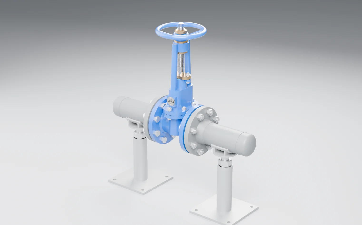
Closed. The gate is seated and the stem is at its lowest. Flow stops — as long as the seats are sound, which closing alone cannot prove.
Deviation library
Components
Explore the equipment
Isolate a line: fully open, it passes flow with almost no restriction; fully closed, it stops flow so the equipment beyond it can be taken out of service. It is a block valve, not a control valve, and is meant to sit at one end of its travel or the other. This one is flanged, with a rising stem on an outside screw and yoke, so how far the stem stands above the yoke shows how far open the valve is without anyone having to turn the wheel. It is mounted between two short pipe spools on adjustable stands, and its tag plate reads GV-054. The model shows the valve, its flanged joints and its supports only — not the line it isolates, the fluid, the pressure class or the materials. Read those from the valve's nameplate, the line list and the P&ID.
Components
BodyGV-054
The pressure-containing casting with the flanged ends and the seats the gate closes against. It holds line pressure whether the valve is open or closed.
Normally: Holding pressure with no weep from the casting or the flange faces.
Gate
The wedge inside the body that the stem lowers across the bore to close it and lifts clear to open it. It seals by being pressed onto the seats, which is why it is meant to be fully open or fully closed, never part-way.
Normally: Fully out of the bore when open, fully seated when closed.
Stem
The threaded rod that carries the gate. On a rising-stem valve its height above the yoke is the position indicator: high is open, low is closed.
Normally: Clean, straight and lubricated, standing at the height that matches the valve's required position.
Handwheel and yoke nut
The wheel and the bronze yoke nut it turns, which drive the stem up or down. Turning clockwise closes the valve.
Normally: Turning freely by hand, with the nut fastened and the wheel undamaged.
Bonnet and yoke
The cover bolted onto the body, with its gasket, and the yoke that rises from it to carry the yoke nut. The bonnet joint is part of the pressure boundary.
Normally: All bonnet bolts in and tight, with no leak at the bonnet joint.
Gland and packing
The packing rings around the stem where it leaves the bonnet, and the gland and bolts that compress them. This is where the moving stem crosses the pressure boundary, and the commonest leak point on any valve.
Normally: Compressed evenly, with no leak along the stem and the stem still free to move.
Flange joints
The gaskets and bolt sets that join the valve's flanges to the pipe spools on each side.
Normally: Bolted to the specified load with the right gasket, and leak-free.
Pipe spools
The short pipe sections either side of the valve, capped at their far ends in this model.
Normally: Undamaged and free of external corrosion.
Pipe supports
The stands and their adjusters under each spool. They carry the weight of the pipe and valve so it does not hang on the flanged joints.
Normally: Adjusted to bear the load, with base plates fixed down.
Valve tag
The riveted plate carrying the valve's number, GV-054, which is how the valve is found on the P&ID and named on an isolation certificate.
Normally: Fixed, legible and matching the P&ID.
Operating states
Open
The gate is lifted clear of the bore and the stem stands at its highest. Flow passes almost unrestricted. The wheel is usually backed off a fraction from the top stop so the valve cannot be mistaken as seized.
Closed
The gate is seated and the stem is at its lowest. Flow stops — as long as the seats are sound, which closing alone cannot prove.
Isolating for maintenance
Closed, locked and tagged under a permit, with the line beyond it depressurised, drained and proven before anyone breaks a joint. A single closed gate valve is the start of an isolation, not all of it.
Being opened or closed
The wheel is turned steadily by hand, watching the stem move. It is not forced with a bar or wrench, and a valve on a hot or pressurised line is opened slowly.
Failure scenarios and safeguards
MOREFlow when closed
The bleed shows the valve is passing before anything is opened, and the isolation is extended.
Causes
- Seats or gate face eroded by being used part-open to throttle
- Debris or scale trapped on the seat
- Gate not fully seated: closing stopped short, or thermal movement since
How it develops
- 01The gate is down and the stem reads closed, but fluid still passes the seats.
- 02The 'isolated' side slowly re-pressurises, or never fully drains.
- 03A joint is opened believing the line is isolated, and releases fluid under pressure.
Safeguards
Isolation to the site standard
Breaking containment is done under a permit, with the isolation the site's standard requires for the hazard — double block and bleed, or a spade or blind — and the line proven depressurised and drained before any joint is opened.
If it fails: A joint is opened against a single closed valve that may be passing.
Valve inspection and maintenance
The valve is inspected and exercised on a schedule: the stem cleaned and lubricated, the packing checked and adjusted, and passing found by test rather than assumption.
If it fails: A seized stem, a weeping gland or a passing seat is found only when the valve is needed.
Lock and tag
The handwheel is locked in position and tagged with the permit, so nobody opens the valve while the isolation depends on it.
If it fails: Someone opens the valve, not knowing the line beyond it is open.
Unmitigated: Loss of containment onto the people breaking the joint.
NOValve movement
The valve is found stiff during routine exercising and freed or repaired while it is not needed.
Causes
- Stem thread or yoke nut dry, corroded or fouled from never being exercised
- Gate jammed in its seats by thermal binding after closing hot
- Packing over-tightened onto the stem
How it develops
- 01The wheel will not turn, or turns without the stem moving.
- 02Someone reaches for a wheel key or a bar and forces it.
- 03The stem bends or the nut strips, leaving the valve stuck part-way and its position unknown.
Safeguards
Valve inspection and maintenance
The valve is inspected and exercised on a schedule: the stem cleaned and lubricated, the packing checked and adjusted, and passing found by test rather than assumption.
If it fails: A seized stem, a weeping gland or a passing seat is found only when the valve is needed.
Valve identified before operating
The valve number on the tag is checked against the P&ID and the permit before the wheel is turned.
If it fails: The wrong valve is operated, and the one that mattered is left as it was.
Unmitigated: A line that cannot be isolated when it must be, in an upset or an emergency.
OTHER THANContainment at the stem
The weep is seen on inspection and the gland adjusted or repacked under a permit.
Causes
- Packing worn by stem movement, or dried out
- Gland bolts loose or unevenly tightened
- Stem scored or corroded where it passes the packing
How it develops
- 01Fluid weeps along the stem where it leaves the bonnet.
- 02Each time the valve is operated the leak washes the stem and grows.
- 03A steady release at the bonnet, beside the person turning the wheel.
Safeguards
Valve inspection and maintenance
The valve is inspected and exercised on a schedule: the stem cleaned and lubricated, the packing checked and adjusted, and passing found by test rather than assumption.
If it fails: A seized stem, a weeping gland or a passing seat is found only when the valve is needed.
Leak detection and response
Area checks, and gas detection where the fluid calls for it, find a leak early, and the response follows the site's emergency arrangements.
If it fails: A leak grows unnoticed until it is large, or ignites.
Unmitigated: A release of the line's contents at head height, toxic or flammable as the fluid is.
OTHER THANContainment at the joints
The leak is found early, the line isolated, and the joint remade with a new gasket.
Causes
- Wrong or reused gasket
- Bolts unevenly loaded when the joint was made up
- Pipe weight or movement hanging on the joint because a support has dropped
How it develops
- 01A stand settles or is never adjusted, and the line's weight moves onto the valve.
- 02One side of a joint opens up and the gasket stops sealing.
- 03Fluid escapes between the flange faces.
Safeguards
Controlled bolting
Flanged and bonnet joints are made up by trained people to a set bolt load and sequence, with the specified gasket, and recorded.
If it fails: A joint is under-loaded, unevenly loaded or fitted with the wrong gasket, and leaks.
Supports set and checked
Pipe supports are adjusted to carry the line's weight and checked after work nearby, so the valve and its joints are not left carrying the pipe.
If it fails: The line hangs on the flanged joints and bends them open.
Leak detection and response
Area checks, and gas detection where the fluid calls for it, find a leak early, and the response follows the site's emergency arrangements.
If it fails: A leak grows unnoticed until it is large, or ignites.
Unmitigated: A release at the joint that grows with pressure, temperature cycling and vibration.
OTHER THANValve operated
The number is checked against the permit and the mistake caught before the wheel is turned.
Causes
- Tag missing, unreadable or not matching the P&ID
- Similar valves side by side on a manifold or pipe rack
- Instructions given by description rather than valve number
How it develops
- 01The valve is picked by position or appearance, not by its number.
- 02The wrong valve is closed or opened.
- 03The line meant to be isolated is still live, or a line meant to be live is shut in.
Safeguards
Valve identified before operating
The valve number on the tag is checked against the P&ID and the permit before the wheel is turned.
If it fails: The wrong valve is operated, and the one that mattered is left as it was.
Lock and tag
The handwheel is locked in position and tagged with the permit, so nobody opens the valve while the isolation depends on it.
If it fails: Someone opens the valve, not knowing the line beyond it is open.
Isolation to the site standard
Breaking containment is done under a permit, with the isolation the site's standard requires for the hazard — double block and bleed, or a spade or blind — and the line proven depressurised and drained before any joint is opened.
If it fails: A joint is opened against a single closed valve that may be passing.
Unmitigated: Work on a live line, or equipment starved or over-pressured by a valve shut in error.