Shell & Tube Heat Exchanger
Multi-pass exchanger with removable bundle, showing fouling, tube leaks and cross-contamination.
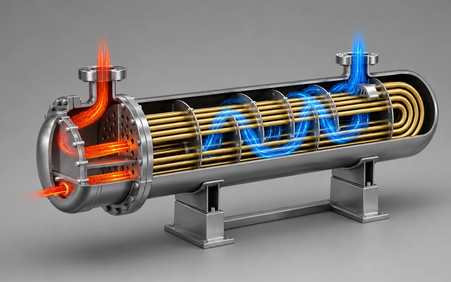
Normal operation. Tube-side fluid enters the inlet compartment, is turned into the bundle by the pass partition plate, returns to the outlet compartment and leaves. Shell-side fluid crosses the bundle on the path set by the four baffles, which also hold the tubes against sagging and vibration. Heat passes through the tube wall; both outlet temperatures sit where the duty requires and the pressure drop on each side is steady — and it is the two readings together, not either alone, that say the exchanger is clean. Read the geometry for what it is: one tubesheet and a pass partition plate is consistent with a two-pass tube side, most probably a U-tube bundle, with the two channel-head nodes as the compartments either side of the partition. A fixed-tubesheet or floating-head unit cannot be ruled out from the geometry alone, and the model says nothing whatever about which stream is hot or which is at the higher pressure. Treat all three as indicative and confirm them against the unit.
Deviation library
Components
Explore the equipment
Transfer heat between two streams without letting them mix. The tube-side stream enters the channel head, is turned through the tube bundle by the pass partition plate and leaves at the temperature the downstream duty requires; the shell-side stream is driven across the bundle by the baffles rather than along it. The tube walls, the tube-to-tubesheet joints and the bolted girth joint are the containment boundary — between the two streams, and between both of them and atmosphere. Which stream is the hotter one and which sits at the higher pressure is a property of the service, not of the geometry: this reference model cannot tell you, so read both off the unit's datasheet before working any case here, and read the deviations below in those terms rather than assuming the shell is the cold, low-pressure side. Tagged as the exchanger E-101. The exchanger itself is what a P&ID tags — its shell, bundle, baffles, tubesheet, gasket and bolting carry no tags of their own — and the instrument and relief tags used on the safeguards below are conventional illustrations of the protection, not tags read from a drawing.
Components
Shell
Contains the shell-side stream and forms the outer pressure boundary around the bundle. Its design pressure and temperature belong to the shell-side service, and are frequently not the same as the tube side's.
Normally: Intact and flooded with shell-side fluid, flowing from one shell nozzle to the other across the bundle.
Tube bundle
Carries the tube-side stream through the shell. The tube wall is both the heat transfer surface and the barrier between the two streams, so it is the one part where a loss of containment mixes the streams instead of releasing them. One tubesheet and a pass partition plate are modelled, which is the arrangement of a two-pass — most probably U-tube — bundle; no rear tubesheet, floating head or return bends are separately named, so the rear-end type cannot be read off this model. Neither can the model say which side is hotter or at the higher pressure. Both are properties of the service.
Normally: All tubes open and flowing, wetted on both sides, with nothing crossing the tube wall in either direction.
Baffle set
Directs the shell-side stream across the bundle rather than along it, and supports the tubes against sagging and flow-induced vibration. Four are modelled.
Normally: In place, giving the intended cross-flow path and holding tube spacing at the unsupported span the tubes were sized for.
Tubesheet
Anchors the tube ends and separates the shell side from the tube side. The tube-to-tubesheet joints are the boundary between the two streams, and are where thermal cycling, crevice corrosion and vibration do their damage.
Normally: Joints tight — nothing passing from the shell space into the channel, and nothing from the channel into the shell space.
Pass partition plate
Divides the channel head into inlet and outlet compartments, so the tube-side stream is made to pass through the bundle instead of short-circuiting from the inlet nozzle straight to the outlet nozzle.
Normally: Sealed against the tubesheet and the channel wall, so the whole of the tube-side flow goes through the bundle.
Channel head, inlet compartment
Receives the tube-side stream from its inlet nozzle and distributes it across the first pass of the bundle.
Normally: Full and flowing at inlet conditions, vented of gas, feeding the pass evenly.
Channel head, outlet compartment
Collects the tube-side stream returning from the bundle and passes it to the outlet nozzle.
Normally: Collecting return flow at the outlet condition, changed from inlet by the duty the exchanger is transferring.
Nozzle flanges
The flanged connections through which the two streams enter and leave, together with any vent and drain points. Six are modelled; the geometry alone does not say which serve the shell side, which the tube side, and which are vents or drains.
Normally: Made up on gaskets and leak-tight, with the connecting pipework supported so no piping load is carried by the branch.
Girth joint gasket
Seals the bolted joint between the channel, the tubesheet and the shell flange. At that joint it is the last barrier between the process and atmosphere, and it is the joint broken every time the bundle is withdrawn.
Normally: Compressed to its seating stress by the bolting, with no weep at the flange face.
Flange bolting
Clamps the girth joint, holding gasket compression against internal pressure and against the movement of the joint through temperature.
Normally: Fully made up and evenly loaded, with no relaxation, and no bolt slackened while the exchanger is live.
Saddle supports
Carry the weight of the shell and its contents into the supporting structure, and locate the exchanger. On a horizontal unit one saddle is conventionally fixed and the other allowed to slide so the shell can grow axially; the model does not distinguish the two.
Normally: Both bearing evenly, the sliding end free to move, and no thermal growth transferred into the nozzles.
Operating states
Startup and warm-through
Both sides vented and filled, then brought up together. The colder stream is established first and the hotter one admitted gradually, so the shell and the bundle change temperature at a rate the joints can carry rather than one dragging the other. High-point vents on the channel and on the shell are closed only once liquid is confirmed: gas trapped in a channel compartment or under the top of the shell leaves part of the surface dry, and a dry surface drifts toward the temperature of the stream on the other side of it instead of sitting between the two. Bolted joints are re-checked warm, because bolt load moves as the metal expands.
Normal operation
Tube-side fluid enters the inlet compartment, is turned into the bundle by the pass partition plate, returns to the outlet compartment and leaves. Shell-side fluid crosses the bundle on the path set by the four baffles, which also hold the tubes against sagging and vibration. Heat passes through the tube wall; both outlet temperatures sit where the duty requires and the pressure drop on each side is steady — and it is the two readings together, not either alone, that say the exchanger is clean. Read the geometry for what it is: one tubesheet and a pass partition plate is consistent with a two-pass tube side, most probably a U-tube bundle, with the two channel-head nodes as the compartments either side of the partition. A fixed-tubesheet or floating-head unit cannot be ruled out from the geometry alone, and the model says nothing whatever about which stream is hot or which is at the higher pressure. Treat all three as indicative and confirm them against the unit.
Reduced throughput
The unit runs below design flow on one side or both. Velocities fall, so solids that were previously swept through settle in the shell-side baffle windows and along the bottom of the shell, and deposits build on the tube bore — fouling accelerates at exactly the point where the duty is easiest to hold. With less flow to heat or to cool, the outlet temperature approaches the other stream's inlet temperature more closely than it does at design, so the exchanger still looks as though it is performing while the fouling resistance grows underneath. Pressure drop is the reading that gives it away.
Controlled shutdown
The stream supplying heat is taken off first, and the other kept running until the bundle has come down with it, so the exchanger cools together rather than one side being quenched. Both sides are then depressurised and drained through the low-point connections. Stopping the cooling stream first leaves a hot bundle blocked in, where trapped liquid expands against closed valves; stopping both at once puts the whole differential across the tube-to-tubesheet joints in a single step. Neither side is left liquid-full and isolated while the other is still at temperature.
Standby and isolation
Isolated, drained or blanketed, and idle — between campaigns, or waiting for the bundle to be withdrawn for cleaning and inspection. Liquid left standing in the shell or in the channel is the condition under which under-deposit and microbially influenced corrosion do most of their damage, so a wet lay-up is a decision taken deliberately, not a default. As the joint cools, bolt load relaxes and the girth and nozzle gaskets can weep on the next pressurisation; the joint is remade with a new gasket and controlled tightening whenever it has been opened, and the exchanger is proved isolated, depressurised and drained before any bolt is slackened.
Failure scenarios and safeguards
NOFlow
Loss of flow shows first as the tube-side outlet temperature running away from its normal value — upward where the other stream is hotter, downward where it is colder — and the operator restores flow or takes the other stream off. Where the side has been blocked in, the thermal relief inside the isolation holds the pressure while that is done; and the isolation sequence is what should have prevented a liquid-full side being shut in against heat in the first place.
Causes
- Upstream isolation valve closed in error, or left shut after maintenance
- Blockage or debris lodged at the channel inlet nozzle or across the tube entries
- Pump trip, or a trip of the upstream unit feeding the tube side
- Control valve failing shut downstream, removing the driving differential
- The tube side blocked in between closed valves while the shell side keeps circulating at its own temperature
How it develops
- 01Tube-side flow stops. The inlet compartment stops delivering, and the inventory standing in the channel and at the tube entries goes stagnant.
- 02Stagnant inventory sits in both compartments and through the bundle, still in thermal contact with the shell side, and drifts toward the shell-side temperature. Which way it drifts is the whole of this deviation, and it is set by the service, not by the geometry.
- 03Where the shell side is the hotter stream: the trapped liquid expands, and the expansion of a liquid in a closed volume raises pressure steeply — that mechanism holds whatever the bundle arrangement is, and it is what generates the pressure. Tube metal climbs toward the shell-side inlet temperature, and if the inventory reaches its boiling point the rise is faster again. In a fixed-tubesheet unit the bundle is additionally restrained by the cooler shell and that differential expansion is carried in the tube-to-tubesheet joints; a U-tube bundle takes that part in its bends instead, which is why the arrangement has to be confirmed against the real unit rather than read off this model.
- 04Pressure carries through both compartments to whatever relief path exists inside the isolation. Where there is no thermal relief in that volume, the tubes, their joints and the girth gasket are the relief path.
- 05The mirror case, where the shell side is the colder stream: blocking in the tube side does not overheat it, it chills it. The stagnant inventory cools toward the shell-side temperature and freezes, waxes, forms hydrate or otherwise solidifies in the bore and in the channel. The flow path is lost rather than overpressured, and a freezing aqueous inventory can split tubes on its own, with no pressure applied from outside.
Safeguards
Outlet temperature alarm and operator responseTAH-101
Annunciates a loss of heat transfer or a loss of flow — how fouling, gas or vapour blanketing, tube plugging, bypassing past the pass partition plate and the sudden loss of one stream usually first show themselves. The operator investigates, and can restore flow, reduce duty, swing to a spare exchanger or shut down.
If it fails: The condition develops unseen and is found later as damage rather than as a deviation. Credit it only where the alarm reaches someone, there is time to act on it, and the required action is unambiguous; where any of the three is missing it is an indication, not protection.
Thermal relief on the blocked-in volumeTSV-101
A relief device inside the isolation valves, sized for the expansion of the trapped liquid inventory rather than for a rupture flow. It is the only device that protects a side which has been blocked in while the other side is still at temperature — a relief valve outside the isolation is not in that volume and does nothing for it.
If it fails: The trapped inventory has nowhere to expand, so pressure climbs until part of the boundary yields and becomes the relief path: a tube, a tube-to-tubesheet joint, or the girth gasket.
Controlled warm-through, cool-down and isolation sequence
Brings the two sides up and down together at a rate the joints can carry, with vents held open until liquid is confirmed; and on shutdown takes the heating or cooling medium off before the other side is blocked in, so no side is left liquid-full and isolated with heat still on it. The rate of change is monitored rather than assumed. Being procedural, it is only as good as the step being followed under time pressure.
If it fails: The bundle and the shell change temperature at different rates and the difference is taken as stress in the tube-to-tubesheet joints and the bolting; or a side is blocked in hot, and what was a thermal deviation becomes a pressure one.
Unmitigated: In the hot case the blocked-in inventory expands until a tube, a tube-to-tubesheet joint or the girth gasket gives way, releasing the tube-side inventory into the shell or to atmosphere — and where the liquid has begun to vaporise, the metal is hot and has already lost strength by the time it fails. In the cold case the bore plugs solid: flow cannot be restored, the plug is thawed or forced with the exchanger still isolated, and split tubes are found on the next pressurisation.
LESSHeat transfer
The duty loss is visible as a drifting outlet temperature together with a rising pressure drop, and the exchanger is taken off line and cleaned at a planned opportunity rather than run to failure. Inspection at that opportunity is what establishes whether the tubes have thinned as well as fouled — the process data cannot show it.
Causes
- Scale, sediment, corrosion product or biological growth building on the tube bore
- Deposits and sludge collecting in the shell-side baffle windows and along the bottom of the shell
- Sustained operation at low velocity, which lets solids settle instead of being swept through
- A stream carrying more solids, or running hotter at the wall, than the cleaning interval was set for
- Gas or vapour trapped at a high point after filling, leaving part of the surface dry
- Leakage past the pass partition plate, short-circuiting flow from the inlet compartment to the outlet compartment without it passing through the bundle
How it develops
- 01A fouling layer builds on the tube surface and adds thermal resistance in series with the wall. The same flows now transfer less heat.
- 02Outlet temperature drifts away from specification while pressure drop rises as the bore narrows. The pair is the signature: a temperature drift on its own is as likely to be an instrument.
- 03Shell-side deposits fill the baffle windows and force flow to bypass part of the bundle. The starved rows see lower velocity still, so they foul faster than the rest, and the fouling becomes self-accelerating instead of reaching a plateau.
- 04Where the deposit sits decides what it does to the metal. A deposit on the side supplying heat insulates the wall from that heat: duty falls and the wall, if anything, runs cooler. A deposit on the side removing heat insulates the wall from its own coolant: duty falls and the wall runs hotter, which is the under-deposit overheating case — the classic boiler waterside one, and the only one of the two where you look for creep and hot-side wall loss. Corrosion is a separate mechanism and works either way, because a deposit shelters stagnant liquid against the metal on whichever side it forms; crevice and under-deposit attack thin the wall there. Wall loss is usually found first at the tube entries, where velocity and turbulence are highest, and at the hot end.
Safeguards
Outlet temperature alarm and operator responseTAH-101
Annunciates a loss of heat transfer or a loss of flow — how fouling, gas or vapour blanketing, tube plugging, bypassing past the pass partition plate and the sudden loss of one stream usually first show themselves. The operator investigates, and can restore flow, reduce duty, swing to a spare exchanger or shut down.
If it fails: The condition develops unseen and is found later as damage rather than as a deviation. Credit it only where the alarm reaches someone, there is time to act on it, and the required action is unambiguous; where any of the three is missing it is an indication, not protection.
Bundle and shell mechanical integrity programme
Scheduled inspection of the bundle for wall loss, cracking and erosion — eddy current or equivalent on the tubes, with particular attention at the tube ends, at baffle contact points and at the hot end — together with thickness checks on the shell and channel, examination of the flange faces, and a recorded decision on whether a degraded tube is plugged or the bundle retubed. It sets the interval before the next failure rather than detecting one in progress.
If it fails: Degradation runs to failure between inspections, and the first anyone learns of the condition of the bundle is a tube opening in service.
Unmitigated: Duty is made up by raising the temperature of the heating medium or the flow rate. Both accelerate the fouling and the wall loss underneath it, and the exchanger is run in that condition until a tube fails in service.
OTHER THANContainment (stream to stream)
Pressure falling on one side while it rises on the other is the signature, and it is alarmed: the trip takes out the higher-pressure source, the exchanger is shut in and isolated, and where the unit was designed with margin across the interface, that margin is what the lower-pressure side is holding while it happens. Where there is no margin, the relief device is carrying the rupture flow on its own.
Causes
- Tube wall thinned by corrosion, inlet-end erosion or under-deposit attack
- Flow-induced vibration across an unsupported span where a baffle is worn, damaged or missing
- Fatigue cracking at a tube-to-tubesheet joint after repeated thermal cycling
- A tube returned to service after inspection recorded wall loss
- A pressure surge on the higher-pressure side
- Mechanical damage during cleaning or bundle withdrawal
How it develops
- 01A tube wall or a tube-to-tubesheet joint opens, and the higher-pressure stream discharges through it into the lower-pressure side. Which of the two is which is a property of this service and not of the geometry — establish it from the datasheet before working the case, because everything that follows changes direction with it.
- 02Where the tube side is the higher-pressure one, the release enters the shell space as a jet that impinges on neighbouring tubes and on the baffles, cutting a second tube and turning one failure into several. Where the shell side is the higher-pressure one, the flow runs the other way — into the bore and straight down it to the channel head.
- 03Pressure on the lower-pressure side rises rapidly and travels out of its nozzles into connected equipment designed for that same lower pressure: the shell and shell-side piping in one direction, the channel heads, the tube-side nozzles and the tube-side piping in the other. The reverse case is real and routinely missed — a steam or high-pressure utility on the shell overpressures the channel head and everything downstream of the tube-side outlet.
- 04If the relief path cannot pass the flow, the weakest part of the boundary yields first — the girth gasket, the bolted joint, or the remaining tube-to-tubesheet joints.
Safeguards
Design margin across the pressure interface
Designing the lower-pressure side to a sufficient fraction of the higher-pressure side's design pressure is credited as protection in its own right, not as a delay: a tube failure raises the lower-pressure side toward a pressure it was built to hold, which is what allows the tube rupture case to be taken out of the relief sizing basis altogether rather than relieved. Relief practice expresses the margin as a proportion of the high-pressure side — the ten-thirteenths basis is the familiar one. Whether it was applied to this unit is a property of its design documentation and must be confirmed there; it is common, which is not the same as present.
If it fails: The interface carries no inherent margin, so protection against tube rupture rests entirely on the trip and the relief device — two active layers, either of which can be unavailable at the moment the tube opens.
High pressure trip on the lower-pressure sidePSHH-101
Detects pressure rising on the lower-pressure side and isolates or shuts down the higher-pressure source, cutting off the flow that is feeding the overpressure. It acts on the cause; the relief device only handles the consequence.
If it fails: Nothing stops the higher-pressure stream crossing the tube wall, so the relief device has to pass the full rupture flow for as long as the leak continues — the duty it is least likely to meet if it was sized on an optimistic hole size, or on a different case entirely.
Relief device on the lower-pressure sidePSV-101
Protects the lower-pressure side of the exchanger, and the equipment connected to it, against overpressure from the higher-pressure stream, relieving to a safe location. It is set at or below the maximum allowable working pressure of the equipment it protects. Whether the tube rupture case is what sizes it depends on the unit's design basis: where the pressure interface carries enough margin, that case may be excluded from the sizing basis and the device sized on the other credible ones. It sits outside the isolation valves and therefore protects nothing that has been blocked in between them.
If it fails: The lower-pressure side — its shell or channel head, their joints and nozzles, and the piping and vessels connected to them — sees the pressure of the higher-pressure stream. Failure then occurs wherever that system is weakest, which is frequently a downstream line or vessel rather than the exchanger itself.
Bundle and shell mechanical integrity programme
Scheduled inspection of the bundle for wall loss, cracking and erosion — eddy current or equivalent on the tubes, with particular attention at the tube ends, at baffle contact points and at the hot end — together with thickness checks on the shell and channel, examination of the flange faces, and a recorded decision on whether a degraded tube is plugged or the bundle retubed. It sets the interval before the next failure rather than detecting one in progress.
If it fails: Degradation runs to failure between inspections, and the first anyone learns of the condition of the bundle is a tube opening in service.
Unmitigated: The lower-pressure side is taken past what it can hold and fails — the shell and shell-side piping where the tube side is the higher-pressure one, the channel head, its girth joint and the tube-side piping where the shell side is. Both inventories go, along with whatever is connected to the side that failed, which is why tube rupture is protected against explicitly rather than assumed survivable.
AS WELL ASComposition
Composition monitoring or routine sampling of the receiving stream picks the ingress up while it is still small — pressure instrumentation will not, and should not be credited here — and the exchanger is isolated and the leaking tubes located, plugged or replaced. Where the pressure hierarchy was set deliberately, the leak has been running into the stream that can tolerate it rather than out into a utility.
Causes
- A pinhole or a weeping rolled joint, too small to move either pressure indication
- Crevice or under-deposit corrosion at the tube-to-tubesheet joint
- Residual leakage past tubes plugged in an earlier repair
- A tube left in service with known wall loss between inspections
How it develops
- 01A tube wall or a rolled joint develops a small leak, and the higher-pressure stream weeps into the other one at a rate neither pressure instrument registers as a change. Nothing here is detectable by pressure, which is the defining feature of this deviation.
- 02The leaked fluid mixes into the receiving stream and is carried to that stream's outlet — across the baffle path to the shell nozzle where the leak runs tube-to-shell, down the bore to the outlet compartment where it runs shell-to-tube. Temperatures and pressures still look unremarkable.
- 03The contamination leaves the exchanger, so the consequence appears somewhere else entirely: a cooling water return and its tower, a condensate or boiler feed system, a storage tank, a catalyst bed, or a reaction where the two fluids are not compatible. Which of those it is depends on which stream is receiving, and that is set by the pressure hierarchy across the tube wall.
- 04The escaping fluid erodes the path it is passing through, so the leak grows rather than settling, and a composition problem becomes a tube failure — at which point the pressure event and the contamination event arrive together.
Safeguards
Composition monitoring of the receiving streamAIT-101
Detects a small tube or joint leak by what it puts into the other stream rather than by pressure: conductivity, pH, hydrocarbon-in-water or dissolved-gas monitoring on the receiving side, or a routine sample at a set frequency. Below the leak rate at which either pressure instrument moves, this is the only detection there is.
If it fails: A weeping tube runs undetected for as long as the contamination is tolerated downstream, which is usually until it damages something — and the hole erodes while it runs, so the leak found late is larger than the leak that started.
Pressure hierarchy across the tube wall
Where the choice exists at design, the more hazardous stream is held at the higher pressure so that any tube leak migrates into it rather than out of it. A utility leaking into a process stream is a dilution and quality problem; a process stream leaking into a utility carries the hazard outside the unit's containment — into cooling water, condensate or boiler feed, and out to wherever that system vents. This is inherent rather than active: it decides which way the leak deviations propagate before any instrument is involved.
If it fails: A leak takes the hazardous stream into the utility system, which has neither the containment nor the detection for it, and the release surfaces at a cooling tower, a vent or a drain some distance from the exchanger. A change in operating pressure on either side can reverse the hierarchy without anything being modified.
Bundle and shell mechanical integrity programme
Scheduled inspection of the bundle for wall loss, cracking and erosion — eddy current or equivalent on the tubes, with particular attention at the tube ends, at baffle contact points and at the hot end — together with thickness checks on the shell and channel, examination of the flange faces, and a recorded decision on whether a degraded tube is plugged or the bundle retubed. It sets the interval before the next failure rather than detecting one in progress.
If it fails: Degradation runs to failure between inspections, and the first anyone learns of the condition of the bundle is a tube opening in service.
Unmitigated: Contaminated fluid is carried into a system with no defence against it; where that system is a utility, the hazard leaves the unit's containment altogether and surfaces at a cooling tower, a vent or a drain. The hole meanwhile erodes until the tube fails outright.
MORERate of temperature change
Controlled warm-through and cool-down, at a rate that is monitored rather than assumed, keeps the differential inside what the joints can carry; the outlet temperature alarm is what tells the operator that one stream has gone while the other is still running, which is the cause that arrives without warning. Any cycle known to have run too fast is followed by inspection aimed specifically at cracked tube-to-tubesheet joints and relaxed bolting.
Causes
- A stream admitted quickly to an exchanger at the other stream's temperature, in either direction
- Warm-through steps shortened or skipped to return the unit to service quickly
- A trip that removes one stream instantly while the other keeps flowing at temperature
- Frequent start-stop cycling of the unit
How it develops
- 01The stream arrives at the channel at full temperature and flow. The nozzle neck and the channel wall change temperature far faster than the heavier metal they are attached to.
- 02The thin tubes follow the fluid quickly while the tubesheet and the shell lag behind, so the bundle and the shell try to change length by different amounts at the same time.
- 03That difference is taken as stress in the tube-to-tubesheet joints, and in a fixed-tubesheet unit in the shell as well. A U-tube bundle absorbs part of it in the bends. This model shows one tubesheet and a pass partition plate, which is consistent with a U-tube arrangement — but the rear end is not modelled, so the arrangement has to be confirmed against the real unit before the case is worked.
- 04Bolt load and gasket seating move through the swing. A joint that was tight cold relaxes, and begins to weep on the next pressurisation.
Safeguards
Controlled warm-through, cool-down and isolation sequence
Brings the two sides up and down together at a rate the joints can carry, with vents held open until liquid is confirmed; and on shutdown takes the heating or cooling medium off before the other side is blocked in, so no side is left liquid-full and isolated with heat still on it. The rate of change is monitored rather than assumed. Being procedural, it is only as good as the step being followed under time pressure.
If it fails: The bundle and the shell change temperature at different rates and the difference is taken as stress in the tube-to-tubesheet joints and the bolting; or a side is blocked in hot, and what was a thermal deviation becomes a pressure one.
Outlet temperature alarm and operator responseTAH-101
Annunciates a loss of heat transfer or a loss of flow — how fouling, gas or vapour blanketing, tube plugging, bypassing past the pass partition plate and the sudden loss of one stream usually first show themselves. The operator investigates, and can restore flow, reduce duty, swing to a spare exchanger or shut down.
If it fails: The condition develops unseen and is found later as damage rather than as a deviation. Credit it only where the alarm reaches someone, there is time to act on it, and the required action is unambiguous; where any of the three is missing it is an indication, not protection.
Bundle and shell mechanical integrity programme
Scheduled inspection of the bundle for wall loss, cracking and erosion — eddy current or equivalent on the tubes, with particular attention at the tube ends, at baffle contact points and at the hot end — together with thickness checks on the shell and channel, examination of the flange faces, and a recorded decision on whether a degraded tube is plugged or the bundle retubed. It sets the interval before the next failure rather than detecting one in progress.
If it fails: Degradation runs to failure between inspections, and the first anyone learns of the condition of the bundle is a tube opening in service.
Unmitigated: Tube-to-tubesheet joints crack from thermal fatigue and leak into the other stream, starting the cross-contamination case from the top; or repeated cycling relaxes the girth joint until the gasket blows out under pressure.
OTHER THANContainment (to atmosphere)
The weep is found by detection or on an operator round while it is still a weep; the exchanger is proved isolated, depressurised and drained before a bolt is touched, and the joint is remade with a new gasket and controlled tightening rather than nipped up in service.
Causes
- Gasket relaxation and loss of bolt load after thermal cycling
- Joint remade after bundle removal with a reused gasket, or without controlled and sequenced tightening
- Damaged or corroded flange face at the channel-to-tubesheet or shell flange
- A pressure surge lifting the joint
- Settlement, or restrained growth where the sliding saddle has seized, putting bending into the shell and its flanges
How it develops
- 01Bolt load falls below what the gasket needs to stay seated, and the joint loses its seal over one segment of the flange face.
- 02The stream inside finds a path across the gasket face and weeps out of the joint at the channel end, where the full tube-side pressure stands at the flange.
- 03The escaping fluid cuts a channel through the gasket, so the leak grows rather than settling. The nozzle joints on the same head are at the same pressure and on the same thermal cycle, and are next.
- 04The release runs down the shell and pools on the saddles and the ground beneath the exchanger — a hot or corrosive liquid on a walking route, or a flammable or toxic stream released at head height in a congested area.
Safeguards
Detection of an external release
Finds a release to atmosphere at a joint while it is still a weep: operator rounds with the exchanger's joints on the route, fixed gas or vapour detection where the stream is flammable or toxic, and drainage and bunding that make a pooled leak visible rather than absorbed.
If it fails: A weep runs unattended and cuts its own path through the gasket, so the first indication is the full release rather than the drip that preceded it.
Controlled joint make-up and breaking
A new gasket every time a joint is opened, flange faces cleaned and inspected, and tightening to a defined pattern and load rather than to feel — with bolt load re-checked once the joint has been through its first heat. On the way in, the exchanger is proved isolated, depressurised and drained before a bolt is slackened.
If it fails: The joint leaks on the next pressurisation, or it is opened live — which is how a routine gasket change becomes a release into the face of the person breaking it.
Bundle and shell mechanical integrity programme
Scheduled inspection of the bundle for wall loss, cracking and erosion — eddy current or equivalent on the tubes, with particular attention at the tube ends, at baffle contact points and at the hot end — together with thickness checks on the shell and channel, examination of the flange faces, and a recorded decision on whether a degraded tube is plugged or the bundle retubed. It sets the interval before the next failure rather than detecting one in progress.
If it fails: Degradation runs to failure between inspections, and the first anyone learns of the condition of the bundle is a tube opening in service.
Unmitigated: The gasket blows out and the inventory releases at the girth joint, at head height and directly in front of anyone standing at the head. Where the response was to tighten the joint live, or to slacken bolts before the exchanger was proved depressurised, that is where people are hurt.